The IEBus on the Honda is going to be time consuming because it is very specific to their cars. So in order to implement my own control I first need to understand enough about IEBus to be able to provide the proper hardware. IEBus is a half duplex two-wire communication bus for vehicles that appears to be commonly used by Japanese car manufacturers such as Honda and Toyota. The two wire bus is differential with a + and - data line. It can support multiple devices on the bus as its message protocol allows the devices to network between each other. It operates in various byte transmission frames which affect bit rate. Beyond just the IEBus physical layer, Honda implements their GA-NET II protocol on top of it. Standalone documentation itself on IEBus is somewhat lacking beyond projects people have done. The best source of reference I have found is from NEC chips that had the controller such as the uPD6708. This chip in particular actually is a means to provide a microcontroller an IEBus controller but getting this chip however does not appear possible.
Packets
The first useful bit of information in the uPD6708 datasheet is the IEBus packet structure. The packet structure contains the fields which allow the devices to communicate between each other in a network freely. It also defines the transfer time as a function of data and frequency.
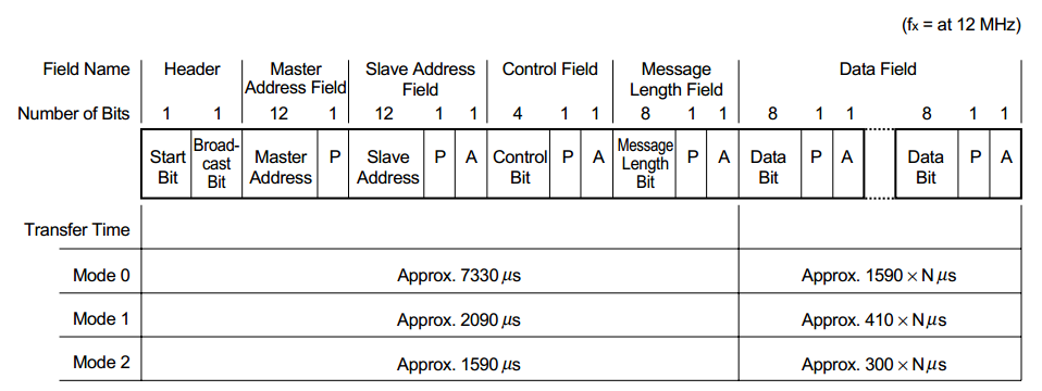
A rundown of the IEBus packet is as follows:
**Start Bit - **A bit that is intended to tell other units that data transmission is starting, this is an attempt at multi-master bus negotiation. Units that want to talk must wait until the talking unit stops.
Broadcast Bit - Broadcasts are messages that do not have to be acknowledged and come in two flavors, group and general broadcast. The slave address field is used to pick groups. Broadcast messages have higher priority on the bus than normal ones.
Master Address - The address of the unit that is talking on the bus.
Slave Address - The address of the unit being talked to. In the special case that broadcast communication occurs. If the address is 0xFFF, it is a general broadcast, if it is any other value, it is a group broadcast. The 4 MSBs of the slave address define the group number in that case.
Control field This is a field that determines what the message is intended to do based on predefined control options.
Message Length- Length of data being transmitted
Waveform
The actual bit waveform for IEBus is even more interesting as shown:
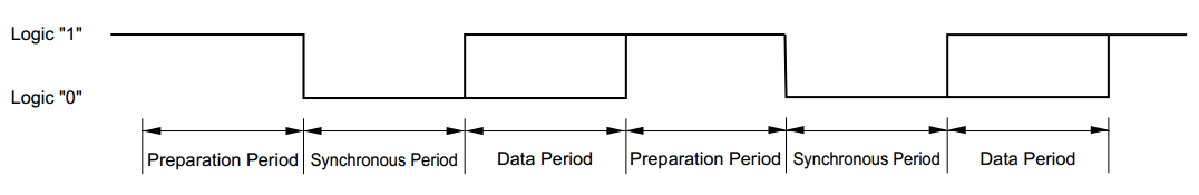
This kind of system of preparation periods of synchronous periods bares a very strong resemblance to Maxim’s 1-Wire protocol which is commonly used with EEPROM and other chips. The preparation period and synchronous period are basically a clock signal conjoined to the same line as data, the talking unit uses the predetermined time frames for preparation period and synchronous period to tell the receiving unit the appropriate time to sample data. Additionally, there does not seem to be a clear specification on the actual timing periods, but going off of the first section of the packet I can compute approximate bit times by just dividing by the number of total bits in the first section. From there the bits are composed of the 3 components, preparation period, sync period and data. So dividing the microseconds/bit by 3 will reveal a rough timing for how long the waveform periods last.
Total of 45 bits, Mode 0 = 7330 us total = 162us/bit = 54us/period Mode 1 = 2090us total = 46us/bit = 15us/period Mode 2 = 1590us total = 35us/bit = 11us/period
These are just really approximate times that I need to determine what clock frequency my microcontroller must run at to keep up on the bus.
Hardware
Now hardware is the second important part to make an IEBus controller and the uPD6708 datasheet provides a good example of how its structured.
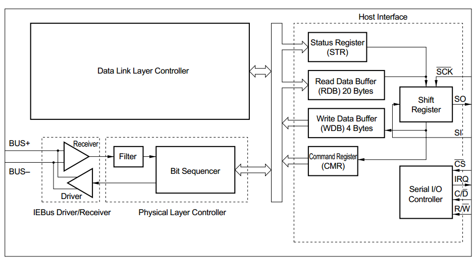
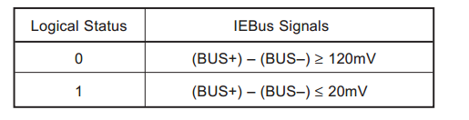
It has a simple receiver/driver pair similar to 485 or CANbus. The rest of the circuit is a filter(most likely glitch filter), a bit sequencer which handles converting between the waveform bit format to data bytes and then the actual logic of the chip. This can all be replicated by a microcontroller fairly easily if it is fast enough to process bits into bytes and determine actions within timing requirements. The actual logic voltages needed for the driver/receiver are also provided as:
Going fowards
Doing some extra research, I found an effort previously made starting in 2006 to decode the IEBus in Acura vehicles which may as well be Hondas. http://acurazine.com/forums/showthread.php?t=346909 from there we can find that Robert Newton succeeded in his endeavors and had made an IEBus micro-controller and released his work here: http://sourceforge.net/p/iebuscontroller/code/HEAD/tree/. A second project that also does IEBus is http://www.sigmaobjects.com/toyota/ by Louis Frigon. They look like good attempts but I want to do better and fanicier.