The EEPROM emulation driver from the ASF provides pretty much all that is required to properly use the feature. Some of the lower level details like configuration are a little unclear from their documentation.
The emulated EEPROM is for the most part just normal flash memory that your application code is also stored in. The emulated EEPROM is addressed at the end chip’s flash memory where a FUSE byte defines “protected” regions of memory.
So as a quick breakdown of how things work, the SAMD20’s flash is organized as rows and each row consists of 4 pages of 64 bytes.

The NVM (Non-volatile memory) operations allows single page reads and writes but erases destroy all four pages in a row. The EEPROM emulator druver Atmel provides deals with row erases and page reads/writes by juggling data for you in a safe manner and it’s the biggest reason to use their API. Application note AT03265 provides a more detailed description.
Chip Configuration
In order to actually use the EEPROM emulation, the SAMD20 must be configured for EEPROM correctly in its fuses. There is a fuse setting called NVMCTRL_EEPROM_SIZE which can be seen with a programmer device like shown below:
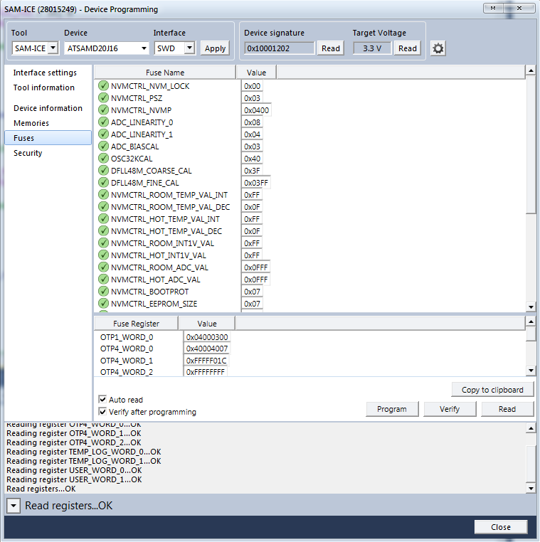
The default value is 0x07 which equates to no eeprom section being configured. The datasheet provides the possible values for the setting in Table 20-3.
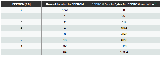
The logical step is to simply need to update NVMTRL_EEPROM_SIZE with a value from the table to allocate an EEPROM section. HOWEVER due to how the ASF driver operates you must have a total of three rows MINIMUM. The reason for the minimum is because the driver needs to reserve a master and a spare row for itself and then it needs at least one row for actual data. Thus the smallest amount of rows allowable with the fuse is with setting 0x04.
Actual EEPROM Size
Atmel’s EEPROM emulator is not the most “space” efficient for storage available in the end. If there are four rows allocated with the fuse bit. Two are gone for the driver’s own usage. The last two rows have a total of 64 bytes * 4 pages total.
However, due to how the driver works. Only two of the four pages are actually usable for data. The driver keeps a backup copy of two pages in the same row.
Also, there is a four byte header at the top of every page. This header means that you only get 60 of the 64 bytes total.
So in the end from the two rows there are only four pages of storage. This provides 240 bytes of EEPROM.
| Allocated # Rows | Actual EEPROM Size (bytes) with ASF Driver |
|---|---|
| 4 | 240 |
| 8 | 720 |
| 16 | 1680 |
| 32 | 3600 |
| 64 | 7440 |
Usage
The actual usage of the emulated eeprom service is just as easy as the application note describes.
The first snippet configures the EEPROM. If it fails to init the EEPROM and gets stuck in the while loop. You must likely did not properly perform the steps above to enable the fuse bits. Otherwise it will hit the second trap when the EEPROM is “fresh” i.e. it has never been used before or it is corrupted. In either case it needs to be erased and setup for use.
void configure_eeprom(void)
{
	/* Setup EEPROM emulator service */
	enum status_code error_code = eeprom_emulator_init();
	if (error_code == STATUS_ERR_NO_MEMORY) {
		while (true) {
			/* No EEPROM section has been set in the device's fuses */
		}
	}
	else if (error_code != STATUS_OK) {
		/* Erase the emulated EEPROM memory (assume it is unformatted or
		 * irrecoverably corrupt) */
		eeprom_emulator_erase_memory();
		eeprom_emulator_init();
	}
}
Reading data is as simple as:
	uint8_t page_data[EEPROM_PAGE_SIZE];
	eeprom_emulator_read_page(0, page_data);
Data is read from page 0 into the page_data buffer on demand.
Writing back data is also simple:
	eeprom_emulator_write_page(0, page_data);
	eeprom_emulator_commit_page_buffer();
That writes back the buffered data to page 0.
More
See Adjusting the linker for use of the EEPROM on SAM M0 devices