After going through both the SAMC21 and the SAME70 family CANBus peripherals in some designs. Here are some lessons learned.
The peripheral itself
Atmel did not design the peripheral. They licensed Bosch’s “M-CAN” peripheral IP and put it into the chip. There is absolutely nothing wrong with this and what better than using the silicon design from the vendor that also creates the CANbus spec? They appeared to license it to gain CAN-FD capability.
The documentation however does suck a little on this peripheral. It is a little complicated and Atmel just copy and pasted the Bosch documentation into their datasheet rather than writing it themselves so the style of documentation doesn’t match their normal one.
SAMC21 vs. SAME70 / SAMV71 peripheral
The peripherals are identical between the two families. However because Atmel has one code style for the M0s and a different code style for M3/M4/M7s. The header definitions for the peripherals use different naming conventions and patterns. The ASF library has less differences but they did do the silly thing of prefixing it “mcan” in the M7 and making it just “can” for the M0.
The INIT flag and errors
The peripheral has an INIT flag. On power-up its “1” which means it is awaiting initialization. You would configure the peripheral and then clear the bit which allows it to run. You would think INIT is its only use….nope!
In CANBus, there is a system of rules to track transmit errors within each CAN device. The end result is if there are enough errors, the peripheral should go “Bus Off” where it stops transmitting.
Bosch decided to implement Bus Off by making it set the INIT flag back to 1.
To continue using the CANBus, you must clear the flag again. But you don’t have to reconfigure the peripheral! No delays are needed too as the peripheral will automatically perform the Bus Off recovery sequence per ISO 11898-1:2015 specification.
I only found this notable because the datasheet doesn’t really emphasize the behavior enough and its just a single sentence at the beginning you have to really think catch
There is unfortunately no way to just tell it to keep chugging along and automatically reinit. So a check somewhere in the micros loop or interrupt is required.
i.e.
static struct mcan_module mcan_instance;

.....

if(mcan_instance.hw->MCAN_CCCR & MCAN_CCCR_INIT)
{
	mcan_start(&mcan_instance);
}
or
static struct mcan_module mcan_instance;
.....
	mcan_enable_interrupt(&mcan_instance, MCAN_BUS_OFF);
.....

/**
 * \brief Interrupt handler for MCAN,
 *   inlcuding RX,TX,ERROR and so on processes.
 */
void MCAN1_Handler(void)
{
	volatile uint32_t status;
	status = mcan_read_interrupt_status(&mcan_instance);

	if (status & MCAN_BUS_OFF) {
		mcan_clear_interrupt_status(&mcan_instance, MCAN_BUS_OFF);
		mcan_stop(&mcan_instance);
		mcan_start(&mcan_instance);
	}
}
Doesn’t work in SAMC21 standby
Its in the Errata but worth mentioning because it can be a big deal if sleep current consumption is a big deal. The peripheral is unable to wake the SAMC21 if in standby. It can wake the micro in the other sleep states.
ASF driver
The ASF driver for the peripheral works but its a little painful to figure out from the cryptic naming convention of registers. There is a lot left to be desired in the implementation provided in the form of missing functions and extensions :/
Clock Configuration
Configuring the clock rate on the SAME70 is messier than on the SAMC21.
SAME70
By default, the system clock feeds the peripheral via PCK5 (peripheral clock 5). This may make configuring the CANbus baud rates strange as your system clock can be a wide range of values which you need to divide down into time quanta. ASF makes the decision to switch it to PLLACK by default (the internal system PLL).
However you can switch it to the UPLLCK which is the fixed USB 480 MHz reference clock. This is done by changing the peripheral clock setting in PMC_PCK5 register using the CSS field to UPLL_CLK.
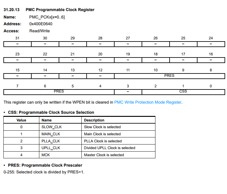
On top of this, you will want to divide down the reference clock further by using the PRES portion of the PMC_PCK5 register.
The issue with ASF is there are no handy defines you can change to configure PCK5 in one predefined spot. In fact, because they manually set the reference clock to pllack you have to edit the ASF driver to fix it.
you’ll find the offending code in /ASF/sam/drivers/mcan/mcan.c
	/* Associate the software module instance with the hardware module */
	module_inst->hw = hw;

	pmc_disable_pck(PMC_PCK_5);

	pmc_switch_pck_to_pllack(PMC_PCK_5, PMC_PCK_PRES(9));
	pmc_enable_pck(PMC_PCK_5);

	/* Enable peripheral clock */
	_mcan_enable_peripheral_clock(module_inst);


	/* Configuration Change Enable. */
	hw->MCAN_CCCR |= MCAN_CCCR_CCE;
If you want to use UPLLCK, you need to modify the ASF driver and use
pmc_switch_pck_to_upllck(PMC_PCK_5, PMC_PCK_PRES(6));with the desired prescalar value as the second arg. Note, the arg is -1 from the actual prescalar result, the macro unfortunately doesn’t do any nice math to hide that part.
SAMC21
Clock configuration in the SAMC21 is more straight forward. You configure a GCLK for the reference clock and set the peripheral to use it like any other Atmel M0 part. The internal 48mhz oscillator makes a perfect reference for the peripheral off the bat.
Baud Rate Configuration
Configuring the baud rate in for all families is where things get more annoying in ASF.
SAME70 / SAMV71
When you create the project. A config/conf_mcan.h file is created with these defines:
/**
 * The setting of the nominal bit rate is based on the PCK5 which is 30M which you can
 * change in the conf_clock.h. Below is the default configuration. The
 * time quanta is 30MHz / (2+1) =  10MHz. And each bit is (1 + NTSEG1 + 1 + NTSEG2 + 1) = 20 time
 * quanta which means the bit rate is 10MHz/20=500KHz.
 */
/** Nominal bit Baud Rate Prescaler */
#define CONF_MCAN_NBTP_NBRP_VALUE    2
/** Nominal bit (Re)Synchronization Jump Width */
#define CONF_MCAN_NBTP_NSJW_VALUE    3
/** Nominal bit Time segment before sample point */
#define CONF_MCAN_NBTP_NTSEG1_VALUE  10
/** Nominal bit Time segment after sample point */
#define CONF_MCAN_NBTP_NTSEG2_VALUE  7

/*
 * The setting of the data bit rate is based on the GCLK_MCAN is 48M which you can
 * change in the conf_clock.h. Below is the default configuration. The
 * time quanta is 48MHz / (5+1) =  8MHz. And each bit is (1 + FTSEG1 + 1 + FTSEG2 + 1) = 16 time
 * quanta which means the bit rate is 8MHz/16=500KHz.
 */
/** Data bit Baud Rate Prescaler */
#define CONF_MCAN_FBTP_FBRP_VALUE    5
/** Data bit (Re)Synchronization Jump Width */
#define CONF_MCAN_FBTP_FSJW_VALUE    3
/** Data bit Time segment before sample point */
#define CONF_MCAN_FBTP_FTSEG1_VALUE  10
/** Data bit Time segment after sample point */
#define CONF_MCAN_FBTP_FTSEG2_VALUE  3
You may assume this is how the canbus baud rate is configured…yes and no. The above defines are used for default baud rate configuration when mcan_init is called inside _mcan_set_configuration.
The driver also comes with a mcan_set_baudrate function which conflicts with the #defines above. It contains hardcoded time quanta settings and attempts to just adjust the baud rate prescalar to make the hardcoded quanta settings work. This could be fine in very simple use cases but the reality is you really want to customize the quanta settings to your design.
/**
 * \brief Set MCAN baudrate.
 *
 * \param[in]  hw          Pointer to the MCAN module instance
 * \param[in]  baudrate    MCAN baudrate
 */
void mcan_set_baudrate(Mcan *hw, uint32_t baudrate)
{
	uint32_t gclk_mcan_value;
	uint32_t mcan_nbtp_nbrp_value;
	uint32_t mcan_nbtp_nsgw_value = 3, mcan_nbtp_ntseg1_value = 10, mcan_nbtp_ntseg2_value = 7;
So how do we fix this mess?
Proper mcan_set_baudrate function:
/**
 * \brief Set MCAN baudrate.
 *
 * \param[in]  hw          Pointer to the MCAN module instance
 * \param[in]  baudrate    MCAN baudrate
 */
void mcan_set_baudrate(Mcan* hw, uint32_t nbrp, uint32_t nsjw, uint32_t ntseg1, uint32_t ntseg2)
{
	hw->MCAN_BTP = MCAN_BTP_BRP(nbrp) |
			MCAN_BTP_SJW(nsjw) |
			MCAN_BTP_TSEG1(ntseg1) |
			MCAN_BTP_TSEG2(ntseg2);
}
and modify _mcan_set_configuration to look like so:
/**
 * \brief set default configuration when initialization.
 *
 * \param hw  Base address of the MCAN
 * \param config  default configuration parameters.
 */
static void _mcan_set_configuration(Mcan *hw, struct mcan_config *config)
{
	mcan_set_baudrate(hw,CONF_MCAN_NBTP_NBRP_VALUE, CONF_MCAN_NBTP_NSJW_VALUE, CONF_MCAN_NBTP_NTSEG1_VALUE, CONF_MCAN_NBTP_NTSEG2_VALUE);
Does this mean we have to do some thinking ourselves on the proper segment widths? Yea…but that’s the entire purpose of the quanta settings! You are meant to tweak them to the application. CANopen for example prefers a SJW value of 1 and sample point at 87.5% . NTSEG1 and NTSEG2 should get adjusted for transceiver propagation delay, etc.
Does this mean we can now use mcan_set_baudrate liberally? No. You have to deal with the Configuration Change Enable system of the peripheral. It’s a secondary bit that turns on/off configuration and protects the settings from inadvertent changes.
To actually change the baudrate you must
- mcan_stop() the peripheral
- Set the CCE flag in the CCCR register manually (no helper function unfortunately)
- Call mcan_set_baudrate
- mcan_start() the peripheral
You could combine this procedure into the custom mcan_set_baudrate like so:
/**
 * \brief Set MCAN baudrate.
 *
 * \param[in]  hw          Pointer to the MCAN module instance
 * \param[in]  baudrate    MCAN baudrate
 */
void mcan_set_baudrate(Mcan *hw, uint32_t nbrp, uint32_t nsjw, uint32_t ntseg1, uint32_t ntseg2)
{
	//mcan_stop() equivalent, used like this because we would need the mcan_module instance the function
	hw->MCAN_CCCR |= MCAN_CCCR_INIT;
	while (!(hw->MCAN_CCCR & MCAN_CCCR_INIT));

	//enable configuration change
	hw->MCAN_CCCR |= MCAN_CCCR_CCE;

	hw->MCAN_BTP = MCAN_BTP_BRP(nbrp) |
			MCAN_BTP_SJW(nsjw) |
			MCAN_BTP_TSEG1(ntseg1) |
			MCAN_BTP_TSEG2(ntseg2);

	//mcan_start() equivalent
	hw->MCAN_CCCR &= ~MCAN_CCCR_INIT;
	while (hw->MCAN_CCCR & MCAN_CCCR_INIT);
}
SAMC21
Suffers from the same problems above as the SAME71. The tweaks are basically the same except for the different defined register names.
FIFO based messaging
The peripheral actually has a few of operation to send and receive CAN messages, in fact the modes can be configured differently for RX and TX. It is up to the particular application to pick the ideal mode of operation. One mode is buffer mode which is akin to the “mailboxes” of the SAM4E,SAM3X and older Atmel micro implementations of CAN, where you have dedicated memory spaces for particular sets of messages to RX and TX from. The other mode is RX/TX FIFOS and TX queue (you can mix and )
One of the most basic modes that there is no example provided for is using FIFOs as RX and TX queues.
Queue has these particular advantages:
- Allows code to dump out messages to send freely in a tx queue
- Allows build-up of messages in a RX queue automatically (no interrupt handler required)
- The rx queue can be processed by a properly scheduled RTOS task or plain micro task.
In a highly active CANbus you may not want a high traffic bus to generate an unpredictable amount of interrupts or you want to minimize processing in interrupts to properly timeshare running code. So if you are going to queue messages anyway, why not let the micro do it for you.
The actual code
For convenience an example project targeting the SAMV71 can be found here: SAMV71 CAN Queue Example
It would be the same exact code for the SAME70 and the SAMC21 would require some porting.
First lets alter config/conf_mcan.h to the below defines
/*
 * Below is the message RAM setting, it will be stored in the system RAM.
 * Please adjust the message size according to your application.
 */
/** Range: 1..64 */
#define CONF_MCAN0_RX_FIFO_0_NUM         0     //configured as standard message FIFO by ASF
/** Range: 1..64 */
#define CONF_MCAN0_RX_FIFO_1_NUM         64    //configured as extended message FIFO by ASF
/** Range: 1..64 */
#define CONF_MCAN0_RX_BUFFER_NUM         0		//disable with 0
/** Range: 1..16 */
#define CONF_MCAN0_TX_BUFFER_NUM         0		//disable with 0
/** Range: 1..16 */
#define CONF_MCAN0_TX_FIFO_QUEUE_NUM     32    //32 is max per datasheet
/** Range: 1..32 */
#define CONF_MCAN0_TX_EVENT_FIFO         8    //disable with 0
/** Range: 1..128 */
#define CONF_MCAN0_RX_STANDARD_ID_FILTER_NUM     32
/** Range: 1..64 */
#define CONF_MCAN0_RX_EXTENDED_ID_FILTER_NUM     16
/** Range: 1..64 */
#define CONF_MCAN1_RX_FIFO_0_NUM         0      //disable with 0, configured as standard message FIFO by ASF
/** Range: 1..64 */
#define CONF_MCAN1_RX_FIFO_1_NUM         64		//disable with 0, configured as standard message FIFO by ASF
/** Range: 1..64 */
#define CONF_MCAN1_RX_BUFFER_NUM         0      //disable with 0
/** Range: 1..16 */
#define CONF_MCAN1_TX_BUFFER_NUM         0      //disable with 0
/** Range: 1..16 */
#define CONF_MCAN1_TX_FIFO_QUEUE_NUM     32		//32 is max per datasheet
/** Range: 1..32 */
#define CONF_MCAN1_TX_EVENT_FIFO         0      //disable with 0
/** Range: 1..128 */
#define CONF_MCAN1_RX_STANDARD_ID_FILTER_NUM     32
/** Range: 1..64 */
#define CONF_MCAN1_RX_EXTENDED_ID_FILTER_NUM     16

/** The value should be 8/12/16/20/24/32/48/64. */
#define CONF_MCAN_ELEMENT_DATA_SIZE         8
The purpose here is to disable the buffer allocation in the ASF driver and maximize our queue size. Why is FIFO1 the only one configured for the QUEUE?
No particular reason other than Atmel examples used FIFO0 for standard messages and FIFO1 for extended, but the hardware doesn’t have any restriction.
Now some code:
/**
 * \brief Configure FIFO1 on the peripheral to accept all extended messages
 */
static void configure_mcan_fifo(struct mcan_module* mcan_mod)
{
	/*
	 *  Setup rx filtering to accept messages into FIFO1 with extended format
	 *  this accepts all messages
	 */
	struct mcan_extended_message_filter_element et_filter;
	mcan_get_extended_message_filter_element_default(&et_filter);
	et_filter.F1.reg = MCAN_EXTENDED_MESSAGE_FILTER_ELEMENT_F1_EFID2(0) |
			MCAN_EXTENDED_MESSAGE_FILTER_ELEMENT_F1_EFT_CLASSIC;
	mcan_set_rx_extended_filter(mcan_mod, &et_filter, 0);
}


/**
 * \brief Queues up a packet for transmission.
 *
 * \param can Pointer to mcan_module that was initialized
 * \param id_value		Message id value
 * \param data			Data array to transmit
 * \param data_length	Length of data to transmit
 *
 * \return True if successfully queued (space available), false otherwise
 */
static bool mcan_send_message(struct mcan_module* mcan_mod, uint32_t id_value, uint8_t *data, uint32_t data_length)
{
	uint32_t status = mcan_tx_get_fifo_queue_status(mcan_mod);

	//check if fifo is full
	if(status & MCAN_TXFQS_TFQF) {
		return false;
	}

	//get the put index where we put the next packet
	uint32_t put_index = (status & MCAN_TXFQS_TFQPI_Msk) >> MCAN_TXFQS_TFQPI_Pos;

	struct mcan_tx_element tx_element;
	mcan_get_tx_buffer_element_defaults(&tx_element);

	tx_element.T0.reg |= MCAN_TX_ELEMENT_T0_EXTENDED_ID(id_value) | MCAN_TX_ELEMENT_T0_XTD;
	tx_element.T1.bit.DLC = data_length;

	for (uint32_t i = 0; i < data_length; i++) {
		tx_element.data[i] = data[i];
	}

	mcan_set_tx_buffer_element(mcan_mod, &tx_element, put_index);
	mcan_tx_transfer_request(mcan_mod, (1 << put_index));

	return true;

}


/**
 * \brief Get a packet from the software reception buffer
 *
 * \param can Pointer to mcan_module that was initialized
 * \param id_value		Message id value
 * \param data			Data array, should be big enough for message, 8 for CAN, 64 for FD. Otherwise data will be dropped on the copy to array (See data_length param)
 * \param data_length	Data buffer size (set before calling the function), this gets updated in the function call to the actual length of data received if its smaller than the max
 *
 * \return True if packet retrieved, false if no packet available
 */
static bool mcan_get_message(struct mcan_module* mcan_mod, uint32_t* id_value, uint8_t* data, uint8_t* data_length)
{
	uint32_t status = mcan_rx_get_fifo_status(mcan_mod, MCAN_RX_FIFO_NUMBER);

	uint32_t num_elements = status & MCAN_RXF1S_F1FL_Msk;
	uint32_t get_index = (status & MCAN_RXF1S_F1GI_Msk) >> MCAN_RXF1S_F1GI_Pos;

	if (num_elements > 0) {
		mcan_get_rx_fifo_1_element(mcan_mod, &rx_element_fifo_1, get_index);
		mcan_rx_fifo_acknowledge(mcan_mod, MCAN_RX_FIFO_NUMBER, get_index);

		*id_value = rx_element_fifo_1.R0.bit.ID;
		if( rx_element_fifo_1.R1.bit.DLC < *data_length ) {
			*data_length = rx_element_fifo_1.R1.bit.DLC;
		}

		for (size_t i = 0; i < *data_length; i++) {
			data[i] = rx_element_fifo_1.data[i];
		}

		return true;
	}

	return false;
}
You can see the implementation is very simple and will allow you send and receive messages rather lazily.
Again, this is purely an example. Every application has a different need, sometimes you don’t care about tossing messages out because your queue is full and sometimes you do want to error handle that situation.